


Lifting and Replacing a Coal Transfer Conveyor Tube
Enerfab, Inc. was hired to complete the lifting and replacing of a conveyor tube for a coal transfer facility using rented Modulift® spreader beams from Lifting Gear Hire.
THE SITUATION
In March of 2015, a 135-foot long conveyor belt at a utility coal transfer facility along the Mississippi River caught fire. The fire buckled the tubular conveyor structure causing it to become unstable. A neighboring 130-foot steel transfer house, which was used to transfer coal from one conveyor belt to another had also caught fire and burned down. With the facility running at less than 50% capacity, Enerfab, Inc. was hired to remove the damaged conveyor tube and install a new one in May, a few months later.
A coal transfer facility’s primary function is to serve as an access point for river barge shipments of coal and railroad or truck overland shipments to coal burning power plants where the coal will be used as fuel to create energy. The coal is delivered to the transfer facility via the Mississippi River or railroad. Once at the facility, high-sulfur coal is mixed with low-sulfur coal to help the plants achieve EPA emissions standards. Once the coal is properly mixed, it is shipped via barge to its designated power plant.
Most power plants do not have train access and those that don’t typically have access to rivers or large bodies of water. Because of this, nearby coal transfer facilities exist as to provide coal fired power plants the coal they require to run their operations.
A large coal transfer facility can accept nearly 200 train cars worth of coal a day.
“We arrived on site and began our evaluation immediately,” Robert Porter, the Regional Manager of Construction said. “This was a project unlike anything we’ve ever done before and it was going to require some ingenuity to fix it. We were going to have to install two cranes, one on both ends of the conveyor belt, lift it at a 15-degree angle, bring it back down, away from the other structure, level it out, and put it back on the ground. Afterwards, we would have to reverse these steps to install the new conveyor structure. It was a fairly simple project and a pretty neat one, too, but there was nothing usual about how we resolved it.”
THE CHALLENGE
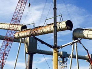
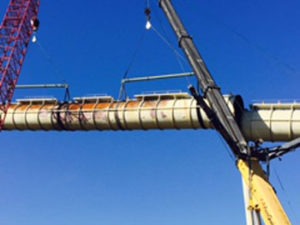
The most complicated aspect of this project came in the form of picking the belt up at a 15-degree angle, which was not the norm for lifting and hoisting equipment that is usually designed to be level. The belt transfers the coal from the ground to the storage silo and rises at a 15-degree angle. Because each end of the tube, as well as each adjacent tube, is cut square in shape and were also built on a 15-degree angle, Porter and his team would be unable to raise the tube level and plumb. To remove the tube, they had to remove it at an angle and then shift it to level in the air before setting it on the ground. This process was reversed for installing the new tube. Not to mention that managers and engineers at the coal handling facility were uneasy at the aspect of hooking two cranes together with a set of roller blocks. They were unsure of the stability of the configuration.
“There simply wasn’t another way to complete this project,” Porter affirmed. “It was honestly a sight to see for everyone involved because the beam was being lifted at a 15-degree angle. It’s not really something you’d see on a normal construction site. But we couldn’t raise the conveyor tube any other way. To do so would risk the tube crashing into the other structures or causing the tube to fall entirely. It was the only safe solution to the problem.”
Aside from that, another issue presented itself in the form of finding a proper lifting beam that could support and accept a 15-degree offset in the spreader bar. The lift angle coupled with limited room to accomplish the task really made Enerfab, Inc. and their contractors question whether this could be done or not.
“What made the lift so challenging was that we wanted to use the same rigging setup and technique for taking the old unit down and putting the new unit in place,” said Irvin Vanderpohl, General Manager of Miami Machine and also an engineer on the project in question. “The old unit was fire-damaged, so the structural integrity was in question and it also contained a large amount of coal. Our primary concern was to ensure that the tube did not collapse when we grabbed ahold of it. The fact that one end of the tube was at a higher elevation added to the challenge.”
THE SOLUTION
The first step in completing the project was crafting the proper lifting plan that would theoretically raise conveyor tube safely. This took nearly a month to complete with many drafts having to be revised due to back and forth arguments and conversations with the numerous engineers aboard the project.
“This lift included experienced engineers with backgrounds in a number of different industries,” Vanderpohl added. “Combined with a skilled team of riggers with a great deal of practical know-how, the team met together with the customer to review the rigging plan. An initial plan was proposed and then modified through a number of joint reviews. This resulted in a safe, clean lift that leveraged the strength of each participant. There was a total of three sets of engineers. The original rigging design team that was provided through the fabricator, the customer engineers, and a 3rdparty engineering firm.”
“It turned into a science project,” Porter surmised. “Not everyone was convinced that the plan would work. We went to the hardware store and picked up some cheap pulleys and rope and we did a little mockup of the construction site to prove our idea would work. Once we got our rigging idea approved, we started our actual engineering. We had a couple of engineering companies on this project. In fact, we had 12 engineers altogether.”
After the rigging plan was approved, Robert needed to find the proper beam that could accept a 15-degree offset. He contacted Lifting Gear Hire and discovered that the project could be accomplished if he rented a MOD 110 modular spreader beam. This particular beam safely allows for such an offset. Now with a proper rigging plan and the right equipment, Robert was able to begin the operation.
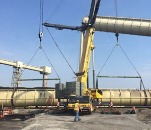
“In lifting the tube, our pick points were 15 feet from each end and the spreader beam was about 33 feet between each set of pick points,” Porter said. “We elevated the tube to 150 feet on the top side and a 130 feet on the bottom side, so it was a pretty elevated lift. With the stresses that were on the tube and where the tube was burnt, it had to be supported in four different locations. That’s the reason we placed two beams on it and two cranes, as well, so we could support it in four specific locations. Otherwise, the conveyor tube could’ve easily collapsed or buckled.”
Adding to overall tension was the slight uneasiness that Robert and his team felt during the entire lifting of the destroyed conveyor tube. The possibility of the tube collapsing and falling in mid-lift was high, but they managed to avoid this by installing a few stiffing beams at each pick point inside the tube, which stiffened the tube enough to where it couldn’t collapse easily on it’s own.
THE RESULT
Once the engineering was approved and the rigging selected it was time for Robert and Steve Vincent, Enerfab Boilermaker Superintendent to turn the work over to the crew to make the lift. The conveyor belt structure was safely lifted and removed in eight hours. Once the damaged tube was safely on the ground, repairs were made to the structural connections on each end of where the new tube was to go. These repairs took several weeks. Then Steve and his crew rigged up to a new conveyor structure that the owner had fabricated. With the rigging in place, they proceeded to lift the new conveyor tube and rest it at a 15-degree angle which took an additional eight hours to complete.
Due to the excellent work they performed, they were hired to build a new transfer house, which involved the removing and replacing of its structural steel. Crafting a new transfer house took nearly six months in addition to the work they had already performed.
The project ultimately concluded in September of 2015.
“After finding the right equipment to do this project and doing a little legwork,” Porter concluded, “we got the facility back up and running completely at maximum capacity. It was an interesting job and I enjoyed working on it. Honestly, we wouldn’t have been able to do without that specific beam we rented from LGH. We originally thought we would have to build one ourselves, but even that wouldn’t have worked. I called LGH and they informed me of a beam that would accept the 15-degree offset. They were the only place that had this kind of beam. To be honest, I’ve been working with LGH for 18 years and I will continue to work with them for another 18 years. They were the only place that had the kind of equipment we needed. If it wasn’t for them, there’s no way we could’ve done this project.”
Because the lift was so unorthodox, the manufacturer and designer of the spreader beam, Modulift® was asked to consult on the project.
“I did have a number of concerns with this lift,” said Anthony Culshaw, Senior Design Engineer of Modulift®. “But nothing that would’ve cause me to advise Enerfab, Inc. to not perform this lift in the manner in which they did. The MOD 110 is a spreader beam that can accept an angle on the drop link of nearly 20 degrees. I was more concerned regarding the use of the snatch blocks, because if used incorrectly, these can be a very dangerous rigging component. Enerfab’s lift would’ve been a concern if the rolling blocks were connecting to the bottom slings to each end of the spreader rather than being connected above the spreader. As the lift was carried out with two cranes and the blocks at the top, they used the blocks correctly which allowed them to adjust the angle of the tube mid-lift. In other words, it was a tandem lift which made the lift stable.”
Special Note: Although it’s highly unusual to use a beam in such a fashion, it was approved by a representative from Modulift®, the beam manufacturer, and they informed the customer and LGH that this particular beam can be used at a 15-degree angle given the special circumstances and specific purpose. Please be advised to contact the manufacturer and a qualified engineer to create a lift plan if you are attempting a similar type of lift.
EQUIPMENT RENTED:
- MOD 110 Modulift® Spreader Beam
- 48” steel chokers
- Sheave blocks
ABOUT ENERFAB, INC.: Enerfab leads the way in providing construction management, capital equipment, maintenance services and technology solutions to the energy industry and other industrial markets around the globe. Enerfab has been recognized as one of the fastest growing privately held companies, employing approximately 4,000 people and operating regional facilities throughout the U.S.A.
ABOUT MODULIFT®: Modulift® are the premier supplier of Spreader Beams for lifting, Lifting Beams, Spreader Frames, and other below the hook heavy lifting equipment. As specialist lifting engineers operating in a niche market, they concentrate on the provision of off-the-shelf, and custom lifting solutions.
ABOUT LGH: Lifting Gear Hire is the largest single organization in North America devoted exclusively to the provision of lifting and moving equipment for rent. LGH holds a comprehensive inventory for hoisting, rigging, jacking, pulling, material handling, and safety equipment. Rental equipment is available from over 20 locations throughout North America, and LGH customers are supported by local Rental Representatives.